My original aim was to provide at least as much function as a typical video cassette recorder, while avoiding dealing with videotapes.
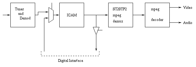
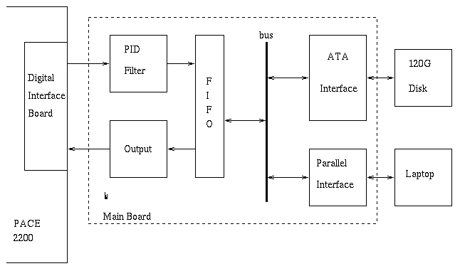
As I already have a PACE 2200 digital satellite receiver, I decided to try to use it as the basis for my PVR. The aim is to extract the mpeg2 datastream at an appropriate point inside the PACE 2200, and save it to a hard disk. For playback, I replace the mpeg2 datastream from the tuner to the mpeg decoder with data read from hard disk. This permits recording and replay with no loss of quality, as no analog signal or MPEG re-encoding is involved. Recording of the original datastream also makes possible recording of additional data in the datastream, such as BBCi interactive content, and recording of multiple programmes at once (so long as they are on the same transport stream i.e. the same transponder.)
As I have neither an understanding of, nor the ability to rewrite the firmware of the PACE 2200, control and user interface of the PVR must be elsewhere. An old laptop proves ideal for this, providing a proper keyboard and display as well as more than enough CPU power. The laptop can tell the PACE 2200 to change channel and other basic functions using the "Link" remote control protocol into the RF2 socket.
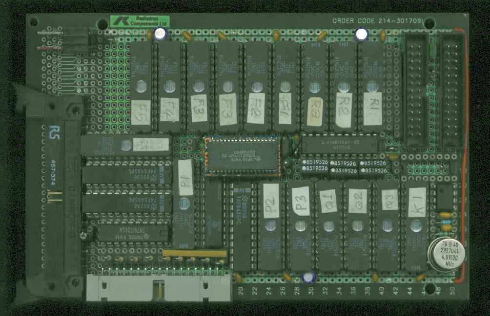
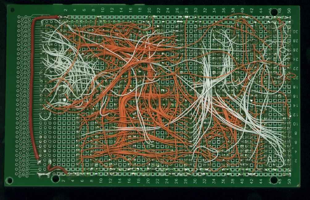
Main board topside / underside.
The PACE 2200 which I own is rev A3.
This is significant because the main firmware runs in the ST20 and so controls the Digital Interface output directly in the A4 revision. In A2 and A3 revisions the Digital Interface is a direct connection to the MPEG transport stream. So in an A2 or A3 revision box, we can use the Digital Interface without needing much cooperation from firmware. The signal to enable output to the Digital Interface port is accessible on the A2 and A3, and unsoldering one chip pin (U205 (a 74LVC574) pin 3) from the board and connecting it to 0V (pin 10 of the same chip) makes it permanently enabled. This is the only modification to the PACE 2200 strictly needed for this project (though mine has several others as well for other purposes, such as a readout of video data rate.)
I don't think an A4 would output anything unless the firmware could be persuaded to enable the Digital Interface.
Other first-generation boxes using the external ICAM chip (such as the Amstrad DRX-100) might also be usable, though without schematics they would be harder to modify.
The Digital Interface within the PACE 2200 connects into its MPEG dataflow like this:
It contains no active components, only some resistors to terminate the cable. Data from PACE 2200 to my PVR is source series terminated (i.e. on this board). Data from PVR to PACE 2200 is source series terminated on the main PVR board, and parallel terminated to ground on this board, this also divides the signals down to the right logic level as the PVR runs on 5V while the Digital Interface uses 3.3V powered chip which could be damaged by 5V signals into them.
The cable from this card to the PVR is ribbon cable, of the style where pairs of wires form twisted pairs except for occasional flat places along the cable for IDC connectors to be fitted. Each signal is paired with a ground for good electrical performance. Ordinary ribbon cable would probably work fine, I just had the "twisty" cable available. Cable reflection or crosstalk problems are (in my experience) bastards to debug, so I tend to go overboard on good cable and termination. My cable is about 12 inches long, but I think it would go much further without problems as the signals look really clean on an oscilloscope (viewed at the receiving end, source series terminated signals always show steps at the transmitting end.)
The cable appears to radiate rather a lot of interference (particularly to my Ch4) so I keep it sandwiched between the bottom of the PVR and the top of the PACE 2200 (both metal). A better solution would be to use small swing differential signalling on the cable (as officially required in the DVB-SPI parallel mpeg cable specification), but this means more chips both ends to convert to/from differential.
Filtering out PIDs for programmes that we are not interested in, as well as discarding all 'filler' packets and other irrelevant data packets, massively reduces the bandwidth being saved to disk compared to recording the whole transport stream. (A whole transponder is 4.2MByte/s, a typical BBC programme audio+video averages around 0.6MByte/s).
The PID filter block tests each transport stream packet's PID, and based on the PID value either passes the packet or drops it. A single byte ($C7) is sent for every dropped packet, so that we can pad out the place with a dummy packet during playback to maintain identical packet timing during playback as in the original transport stream being recorded. (As I have no visibility of the FIFO fullness within the PACE 2200, the only way to prevent overruns is to supply playback data at exactly the same rate at which it was originally broadcast.)
An 8Kx1 (bit) sram contains one flag per PID value, permitting any subset of PID values to be passed or dropped.
This section takes three 22V10 PALs ( R1 R2 and R3 ) plus the 8Kx1 sram.
The FIFO is also useful when the laptop is interpreting data (such as EPG). Even if the laptop is slow to process data, at least one FIFO-full can be acquired before an overrun occurs, so a decent chunk can be processed in one go before software grabs another chunk.
The FIFO is logically divided into 16 sections of 8Kbytes each, for the purposes of tracking how full it is. The top 4 bits of the read and write addresses are compared, to give a status of 0 to 16 sections full. Zero is considered "empty" and Sixteen is "full", these status signals are used by filling and emptying agents for flow control.
The SRAM is arranged to do one write and one read cycle within every clock cycle, so it can simultaneously fill and empty. This uses both clock edges and an external RC delay element to generate the SRAM control signals (not a particularly elegant design, but it works well enough so long as the clock is close to 50:50 duty cycle.)
This section takes six 22V10 PALs ( F1 F2 F3 F4 F5 with F3 being used twice) plus the 128Kx8 sram and a 74F543 (bidi data latch).
Possibly a newer laptop make would be better.
I use the parallel port in EPP mode (which can transfer 4 bytes in one 32-bit CPU IO cycle) which on my laptop can achieve about 250kByte/s. Newer laptops with DMA on the parallel port, used with a much shorter cable, could probably achieve rather more.
Getting the parallel port of a Thinkpad 350 into EPP mode was quite a challenge, as it's not documented by IBM as possible, and finding the databook for the Intel i80360 chipset it uses is difficult (even finding a reference anywhere that the databook exists is hard! Do Intel have something to hide?)
The PVR looks like an EPP device with 16 registers (only bottom 4 bits of address decoded). Ten of these map to the ATA PIO registers, the rest are available for PVR logic use. The address map is:
| 0 | ATA data register (low half) |
| 1 | ATA error/feature register |
| 2 | ATA sector count register |
| 3 | ATA sector number register |
| 4 | ATA cylinder low register |
| 5 | ATA cylinder high register |
| 6 | ATA device register |
| 7 | ATA command/status register |
| 8 | ATA data register (high half) |
| 9 | spare |
| A | spare |
| B | Control register 2 |
| C | FIFO access |
| D | PID Filter SRAM access |
| E | ATA alt status/device control register |
| F | Control register |
This section uses three 22V10 PALs ( P1 P2 and P3 ), plus a 74LS245 to drive the cable and a 74LS273 for the Control register.
PIO cycles are generated from accesses on the Parallel Port interface, these issue disk commands or read disk status.
DMA cycles (for data transfer) are generated in responce to DMA requests from the disk, and are routed to the FIFO. Whether the last command issued was a read or a write is used to determine whether the DMA cycle is a write into the FIFO or a read from it. Since DMA cycles are 16 bits wide, and the FIFO is 8 bits wide, two FIFO accesses are needed to perform one DMA cycle. (Implementation details mean it actually takes 3 clocks to write 2 bytes into the FIFO, but only 2 to read 2 bytes from it.)
This section uses one 22V10 PAL ( D1 ) and two 74F543 bidi data latches.
A standard 120GByte Hitachi disk (7200rpm I think) is attached to the ATA interface. Early experiments were done with much older disks (not recommended as some of my older disks don't support DMA and wouldn't work!)
My software sets the drive to spin down after 5 minutes of inactivity.
This section also generates the MPEG "start" signal, which must be high for the first byte of every 188 byte transport stream packet (the $47 byte). This comes from a divide-by-188 counter. To synchronise it to the start of packets, it sticks at 0 if the data byte is not $47, this will recover correct alignment automatically within a few packets after a data mis-alignment.
The outgoing bus is series terminated to drive into the cable to the PACE 2200.
This section uses three 22V10 PALs ( Q1 Q2 and Q3 ).
Interestingly, the mpeg clock from the Digital Interface is not at 4.583333 MHz, but is a little higher (between 5 and 6MHz). The change appears to happen inside the ICAM.
A TL7705 5V power sense chip provides a clean power-on-reset. (Without this, the PVR tended to power on in "playback" mode which upset the PACE 2200's search for the default transponder.)
A fan (12V one from a PC cpu) provides cooling. The temperature of both PSU and hard disk were unpleasantly high without it, despite the case having a lot of ventilation holes in the base and rear. I used to run it with a series resistor slows it enough to keep the noise down, but one day I had a power cut and the fan failed to start when power came back, leading to a worryingly hot box. I have now upgraded to a thermister sensor that controls fan speed (based on PSU heatsink temperature), one notices it speed up when the disk comes on and power consumption goes up. (The fan is still slightly irritating in a quiet room.)
Most of the logic is put into Cypress PAL22V10-25WC programmable devices, which, thankfully, are UV-erasable as I've had many revisions during the course of this project. Their 25ns propagation delay is quite slow by modern standards, but as the clocks we're dealing with are around 5.5MHz max, are easily fast enough. I used PALASM to compile them.
Here's a pinout map of the board (viewed from wiring side) and the corresponding component layout. Decoupling capacitors are 0.1uF (yellow on photo) or 16uF (purple on photo).
A 1000pF capacitor is used between the PAL supplying the signal and the cable to the PACE 2200, to block any DC that is present (if RF2 power is enabled in the PACE menu) and to attenuate the signal a bit.
Click here for more details on the protocol.
My software is not really user-friendly, and not well written, but does the job adequately.
Main screens are:
All times are currently in GMT (which is what the EPG uses). I'm getting used to this, but it would be nice to support BST display.
Series link currently doesn't work. This is a consequence of me being unable to acquire service data while a recording is in progress, and the link only being transmitted in "now" (and not "next") data so I can't catch it just before starting recording.
The laptop is responsible for knowing what is where on the 120G hard disk in the pvr, this directory is held on the laptop's disk (and old versions backed up so I don't lose everything due to software screwups.) The filesystem is slightly unusual in that one block of mpeg data may belong to more than one recording (for the scenario where several recordings are made simultaneously).
I've found that Pace box firmware (level 1.3.20 1.2S4F9 3.3a.6) has a new problem where it jams up and gives a "technical problem with this service" banner on all channels. (This appears to be provoked by replay of old recordings where the current PIDs for the channel differ from those in the recording.) As far as I can see, the box loses interest in its tuner and fails to tune in any transponder when one changes channel. After missing an episode of "24" due to this, I now have a routine to unjam it (switching to an "Other Channels" service does this, for some reaon) if the right transport stream is not coming through when I start recording.
In case you're interested, here are the Pascal source files (a snapshot from August 2005):
The Digital Video Broadcasting (DVB) specifications provide detailed information on the "Service Information" included within broadcast transport streams. This includes the "Now" text for the programmes currently being transmitted, as well as other Event information and many other bits of information. DVB documents are freely available on the ETSI website. The most useful is ETSI EN 300 468 V1.4.1 (2000-11).
I got my PACE 2200 service manual and schematics from Grandata. CPC also used to stock it. I've heard that it's harder to find these days, now the box is somewhat obsolete.
Last Revision of this page: 2006-12-09